Hydraulic Cylinder Solutions Expert
Efficient, Durable & Energy-Saving
End-to-end hydraulic cylinder solutions for excavators, dump trucks & presses. Engineered to reduce downtime and operating costs.
Our Hydraulic Cylinder Product Range
Precision-engineered cylinders for every heavy-duty application. Hover to explore specifications.
Ever-power Singapore
Hydraulic Cylinders Co., Ltd
Ever-power Singapore Hydraulic Cylinders Co., Ltd is a professional manufacturer of hydraulic cylinders with independent R&D and design capabilities. Founded in 2002, we have built a complete production ecosystem spanning China (headquarters & main factory), Singapore (branch office), Thailand, and Vietnam.
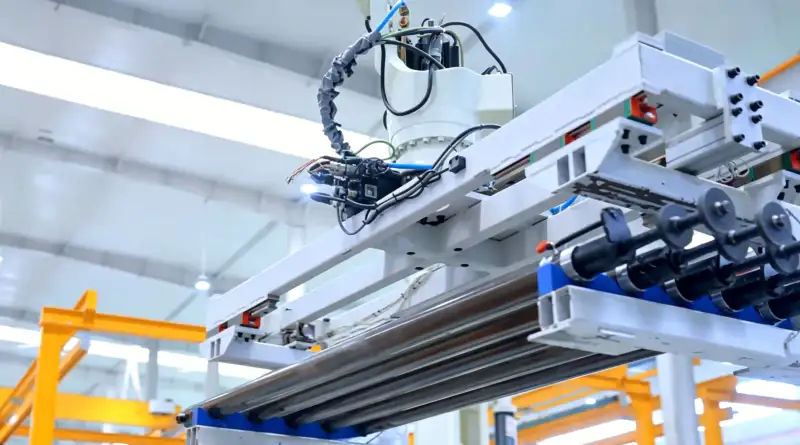
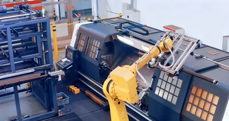
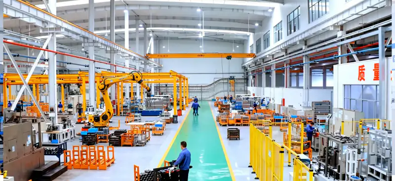
Our facilities cover 20,000+ square meters and house 170+ sets of advanced equipment including CNC machine tools, machining centers, welding systems, and specialized testing apparatus. With over 100 skilled employees — including senior engineers and certified quality inspectors — we deliver end-to-end solutions from concept to mass production.
Our products serve agricultural machinery, construction equipment, vehicles, road engineering, and specialized industrial applications worldwide. We are ISO/TS16949 certified and committed to "people-oriented, continuous innovation, and customer satisfaction."
Take a VR Factory Tour
See Our Production Lines in Action
Experience our state-of-the-art manufacturing facilities from anywhere in the world. Walk through our CNC workshops, welding stations, and quality inspection labs — all in immersive 360°.
Hydraulic Cylinder Structure Breakdown
Hover over each component to learn about its function and material specifications in our precision-engineered hydraulic cylinders.
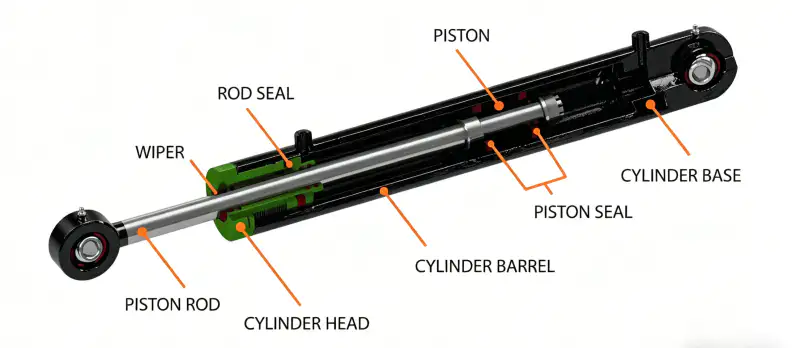
Piston Rod
Chrome-plated high-strength steel rod (typically 45# steel or 40Cr) that transmits force from the hydraulic fluid to the external load. Surface hardness ≥ HRC 60 ensures wear resistance and corrosion protection.
Wiper Seal
Polyurethane or nitrile rubber seal mounted at the rod exit. Prevents external contaminants (dust, moisture, debris) from entering the cylinder barrel, extending seal life and preventing scoring damage.
Rod Seal
Primary pressure seal (PTFE + NBR composite or polyurethane) that prevents hydraulic fluid leakage along the piston rod during extension and retraction. Critical for maintaining system pressure and efficiency.
Cylinder Head (Gland)
Precision-machined steel or ductile iron component that guides the piston rod and houses the rod seal, wiper, and bearing. Threaded or bolted to the cylinder barrel to allow seal maintenance access.
Cylinder Barrel
Honed seamless steel tube (ST52 or 27SiMn) with internal surface roughness Ra ≤ 0.4μm. Contains pressurized hydraulic fluid and provides the bore for piston movement. Wall thickness calculated for working pressure up to 35 MPa.
Piston
Cast or forged steel disc that divides the cylinder into rod-side and cap-side chambers. Transfers hydraulic pressure into linear mechanical force. Features internal passages for cushioning and pressure equalization.
Piston Seal
Double-acting seal (typically NBR, FKM, or PTFE-based) mounted on the piston OD. Prevents fluid bypass between the two pressure chambers, ensuring maximum force output and directional control accuracy.
Cylinder Base (Cap)
Welded or threaded end closure that houses the port connection for hydraulic fluid entry/return. Integral mounting eye or flange for attachment to machinery frame. Designed to withstand full system pressure plus safety factor.
How Does a Hydraulic Cylinder Work?
Understanding single-acting and double-acting hydraulic cylinder principles — from fluid pressure to linear mechanical motion.
Single-Acting Hydraulic Cylinder
Extension PhaseDouble-Acting Hydraulic Cylinder
Extension PhaseFluid Pressurization
The hydraulic pump delivers oil under high pressure (10–35 MPa) to the cylinder. Single-acting: only Port A. Double-acting: Port A or B depending on direction.
Piston Force Generation
Pressure acts on piston area: F = P × A. Single-acting uses full bore area (A₁). Double-acting uses A₁ for extend, annular area (A₂) for retract.
Return Mechanism
Single-acting: internal spring or external load pushes rod back. Double-acting: pressurized fluid enters opposite port for controlled retraction.
Cycle Control
Directional valve manages flow. Single-acting simpler for push-only tasks. Double-acting enables precise bidirectional control for complex automation.
Key Force Formulas
A₁ = Full bore area | A₂ = A₁ − rod area (annular)
Single-acting: spring return force must overcome load. Double-acting: F₂ ≈ 60–80% of F₁.
Trusted by Industry Leaders Worldwide
Our hydraulic cylinders power equipment for the world's most demanding OEMs and machinery manufacturers across 50+ countries.
Pre-Shipment Quality Inspection
Every hydraulic cylinder undergoes a rigorous 7-step testing protocol before leaving our factory. Zero defects, guaranteed performance.
1 Dimensional Inspection
Bore diameter, rod diameter, stroke length, and overall dimensions verified against CAD drawings using CMM and digital calipers.
2 Surface Roughness Test
Piston rod chrome plating and barrel honing surfaces measured with profilometer. Chrome layer thickness 25–35μm.
3 Welding Quality Inspection
All weld seams inspected via ultrasonic testing (UT) and dye penetrant testing (PT). No cracks or porosity permitted.
4 Seal & Assembly Check
Seal groove dimensions, seal material verification (NBR/Viton/PTFE), and assembly torque checked. No seal twisting allowed.
5 Pressure Test (Hydrostatic)
Cylinder pressurized to 1.5× working pressure and held for 10 minutes. No leakage or pressure drop > 2% permitted.
6 Functional Stroke Test
Full extension and retraction cycles at rated pressure and flow rate. Smooth operation, no sticking, no abnormal noise.
7 Final Documentation
Inspection report, material certificate, pressure test certificate, and traceability barcode generated. Data archived for 10 years.
Certified Quality Assurance
Our inspection protocols align with international standards to ensure every cylinder meets or exceeds OEM specifications.
Custom Hydraulic Cylinder Solutions
From concept to production, we engineer hydraulic cylinders precisely tailored to your machinery specifications and operating conditions.
Our Customization Process
6-step streamlined workflow from inquiry to delivery
Need a Custom Hydraulic Cylinder?
Send us your technical requirements — bore, stroke, pressure, mounting style — and our engineers will respond with a tailored solution within 24 hours.
Hydraulic Cylinder Selection Guide
7 critical parameters to determine before ordering. Use this checklist to ensure you specify the right cylinder for your application.
Bore Diameter (mm)
The inner diameter of the cylinder barrel determines the force output. Larger bore = greater force at the same pressure.
Common: 40–200mmRod Diameter (mm)
Affects retraction speed and buckling resistance. Thicker rods withstand higher side loads and bending forces.
Common: 20–140mmStroke Length (mm)
The total travel distance from fully retracted to fully extended. Must match your machinery's required movement range.
Common: 100–3000mmWorking Pressure (MPa)
System operating pressure directly impacts force output and material selection. Higher pressure requires thicker walls.
Common: 16–31.5 MPaMounting Style
How the cylinder attaches to your machine frame and load. Determines load distribution and installation geometry.
Clevis / Flange / Trunnion / FootApplication & Environment
Operating temperature, exposure to chemicals, dust, or seawater affects seal material and surface coating choices.
-40°C to +200°CSpeed & Cushioning
Extension/retraction speed and end-of-stroke cushioning requirements to prevent impact damage and noise.
0.1–0.5 m/sPro Tip
Always provide a sketch or photo of your existing cylinder (if replacing) or the installation space dimensions. This accelerates quoting accuracy by 80%.
Include Drawing → Faster Quote4-Step Decision Workflow
Follow this sequence to narrow down your cylinder specification
Define Load
Calculate required force (F) based on load weight and mechanical advantage. Add 20% safety factor.
Check Pressure
Confirm your hydraulic system pressure. Use F = P × A to solve for required bore diameter.
Measure Space
Record available installation length (retracted) and required stroke. Add 10% buffer for fittings.
Match Mounting
Select mounting style based on load direction, pivot requirements, and frame attachment points.
Quick Reference: Bore vs. Force at Common Pressures
Use this table to estimate required bore diameter based on your load and system pressure
| Bore (mm) | Area (cm²) | Force @ 16 MPa | Force @ 21 MPa | Force @ 31.5 MPa |
|---|---|---|---|---|
| 40 | 12.57 | 20.1 kN | 26.4 kN | 39.6 kN |
| 50 | 19.63 | 31.4 kN | 41.2 kN | 61.8 kN |
| 63 | 31.17 | 49.9 kN | 65.5 kN | 98.2 kN |
| 80 | 50.27 | 80.4 kN | 105.6 kN | 158.3 kN |
| 100 | 78.54 | 125.7 kN | 164.9 kN | 247.4 kN |
| 125 | 122.72 | 196.3 kN | 257.7 kN | 386.6 kN |
| 160 | 201.06 | 321.7 kN | 422.2 kN | 633.3 kN |
| 200 | 314.16 | 502.7 kN | 659.7 kN | 989.6 kN |
Need Help Selecting the Right Cylinder?
Our engineers will review your application and recommend the optimal specification — free technical consultation.